|
|
Dentron GLA-1000 Conversion, Modification With 4 × PL/EL-519 or 2 × GI-7B  23-aug-2013 With an other input circuit. 23-aug-2013 With an other input circuit.Partly finished conversion with a doubling power supply, a 12.6 VAC filament transformer and 2 × GI-7B. You may possibly build a HF amplifier with the information in this article.DESCRIPTIONBy modifying this amp were minimal changes to the original design and as far as possible minor initial components used.The pictures are of the (my) older model 80, 40, 20 and 15 m Dentron GLA-1000 (Plane, no tuned input) HF linear amplifier. The export model had not a 10 m imprint on the front but the band switch was equipped with a fifth state allowing an easy extension to 10 m. It was already done in my GLA-1000. That type is a compact little amplifier, size 28.5 × 14.5 × 34 cm, w × h × d. The depth includes the outward-blowing fan to the rear. These PA's were equipped with American 6MJ6, 6LQ6 and 6JE6C line output tubes. They are randomly to be used but it is better if all runs with equal quiescent currents. They cost a fortune if you can find them. Depending on the brand, the quality of the tubes is moderate to reasonable. They have the same sockets as an EL/PL519 only the pen contacts are different. My experience is that these European tubes appear to be much more robust in a HF amplifier than the American types. The latter have more flashovers after a long unused period. The tubes are also troubled with flashover with more than 50 W from the exciter and then the 230 VAC fuse blows. Unfortunately, the manufacturer did not fit a protection fuse and series resistor in the anode circuit so that the tubes can become defective. The rapid deterioration of the tubes was a common phenomenon. In the later versions a relay with three change over contacts was mounted and on transmit the third contact activate a zenerdiode for the correct idle current.CUT-OFFSome plane Dentron GLA-1000 series amplifiers did not have a "cut-off" circuit to reduce the cathode current in receives mode. This had two disadvantages: they dissipate a continuous power of 80 W and the amplifier was "on" without an output load. In the latter case a chance for random oscillations was not excluded. With the increased idle current the tubes worked near their anode dissipation and worn out faster than usual.With this mod there is no need for a 3rd change over relay contact. There is only one component to be added.A 27 kΩ resistor cuts off the cathode current when the amplifier is stand by. There is still about 300-500 μA idle current, eventually mount more than 27 kΩ for minimum current. Relay K1A contacts short cut the resistor when the amplifier is keyed allowing D1 to hold the idling plate current via RFC1. The latter isolates the RF driving signal from ground (via C7). Two paralleled capacitors were installed in the relay lead to the "RF in" input preventing DC current flowing into the transmitter. Choke RFC1 is wired from that relay contact to the bypassed end of the zener diode.GLITCH PROTECTION There is no failure mode of "glitch" protection and it is a matter of time before the amplifier fails for a number of reasons or shortcomings. Update the PA with the marked components. The extra 4.7 nF capacitor parallel to C8 improves the decoupling of the anode choke RFC6 on 80 m. TEST WITH 4 × PL519Because the American sweep tubes has the same socket as an EL519 a modification would be a piece of cake. The ever-flashing 6LQ6 tubes (with simultaneously a blown main fuse) were replaced by PL519's, so it was easy and safe to see how the amplifier would react in the various bands. WIDEBAND INPUT CIRCUIT & EL519'sThe static input impedance of the cathode in a grounded grid circuit can be calculated if the valve characteristics relating to the specific circuit are known. The dynamic input impedance (during working conditions) is often higher. Furthermore it varies during a SSB transmission because the driver (the transceiver) is delivering power varying between say 0.1 W (the suppressed carrier) and about 100 W. The input- and output impedance of the amplifier are constantly varying and the driver sees a constantly varying load. If the internal controlling system (ALC) cannot handle this, a distorted signal will be generated in the transceiver. With a fast reacting SWR-indicator between TX and PA, one will see a constantly varying SWR. The input impedance of the PL519's in the circuit chosen by me was not known. With an experimental test rig, I have tried to obtain some relevant data. It turned out that these data were different for every amateur band, roughly averaging 17 Ω–27 Ω and with some guessing, I found that for 4 valves in parallel, the average real part was 22 Ω, say 25 Ω.In most cases a tuned circuit between driver and final stage is recommended. By way of flywheel-action this tuned input-circuit will, to a degree, level out the quite variable input impedance, thereby preserving a reasonable match and thus linearity and output of the driving transceiver. The tuned input circuit also shortens the HF return path between anode and cathode by preventing this HF current to follow the longer path via the transceiver. As modern transceivers have more than sufficient power, the "flattening" of the input impedance may also be obtained by extra loading (swamping) the input-circuit with a resistance or suitable wide band combination, in which excess driving power can be absorbed. This also helps in lowering the HF return-path impedance.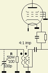 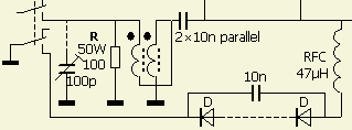 Test 1 × GI-7B with a smaller cooler for the anode. The tube was temporary mounted on a base of a defect 3-500Z for eventually testing in my FRI750 PA Test with minor modifications of the schematic. The blue colour marks the details. [img]https://pa0fri.home.xs4all.nl/Lineairs/GLA1000/gi7btestf2.jpg[/img] Test with 2 × GI-7B and an external input circuit (ATU) to obtain SWR = 1 on all bands. Anode supply was about 850 V on load. [img]https://pa0fri.home.xs4all.nl/Lineairs/GLA1000/original-sockf1.jpg[/img] [img]https://pa0fri.home.xs4all.nl/Lineairs/GLA1000/original-sockf2.jpg[/img] An original socket for the GI7B. [img]https://pa0fri.home.xs4all.nl/Lineairs/GLA1000/feedbackrs.gif[/img] This converted amplifier requires less drive than the 100 watts many transceivers provide. Addition of a ± 10 Ω/15 W non-inductive resistor (R) is a simple way of correcting the overdrive. An RF-negative-feedback voltage will be developed across R when the GI-7B amplifies RF and reduces the driving voltage developed at the cathode. The negative feedback also improves amplifier linearity by reducing IMD to a level lower than that attainable when the tube is driven at its rated driving power without the feedback resistor, it helps to keep tube operation in its linear region. R absorbs the excess driving power as heat. The input impedance without a input circuit is ± 50 Ohm and SWR ≤ 1.7.EXPERIMENTAL VARIABLE INPUT CIRCUIT WITH 1 KNOB[img]https://pa0fri.home.xs4all.nl/Lineairs/GLA1000/gi7binputf.jpg[/img] [img]https://pa0fri.home.xs4all.nl/Lineairs/GLA1000/gi7binputs2.gif[/img] [img]https://pa0fri.home.xs4all.nl/Lineairs/GLA1000/t68-2f.jpg[/img] I have not tested this (F1FRV) modified alternative input circuit, but you can do it yourself. TEST 2 × GI-7B WITH DOUBLING 2100 V SUPPLY
[img]https://pa0fri.home.xs4all.nl/Lineairs/GLA1000/feedbackrf.jpg[/img][img]https://pa0fri.home.xs4all.nl/Lineairs/GLA1000/testhvf.jpg[/img]
Testing the "final" circuit with 10 Ohm feed-back and an (fig») temporary external HT doubling components, 6 × 220 µF/450 V and 6 × 1300 V/1 A. Key-down output was 700–850 W with 1500 V on load. Average CW/1850 V, SSB/2000 V and off load ± 2100 V. An 24 zener diode holds the idling plate current flow to around 100 mA. The dissipation of the tubes is overrated in this design but the transformer is not e.g. the output should be limited to 700–750 W. Therefore the feedback resistor "R" was increased to 25 Ohm. Two 50 Ohm/30 W non inductive "chip" resistors («fig) in parallel on a small heath sink ware mounted in the airflow of the blowing fan. Test with temporary wiring and alternative cathode/filament connections with hose clamps and tool clips. [img]https://pa0fri.home.xs4all.nl/Lineairs/GLA1000/socketf2.JPG[/img] Standard tool clips used as connectors. [img]https://pa0fri.home.xs4all.nl/Lineairs/GLA1000/socketf3.jpg[/img] The improved wiring. The elevating of the voltage from 1050 to 2150 V increased the plate load impedance.[img]https://pa0fri.home.xs4all.nl/Lineairs/GLA1000/draadf1.jpg[/img] Remove the 20-15-10 m coil L1 and wind another coil with the same wire size or with standard 6 mm² tinned solid copper wire (fig ± 2.76 mm diameter»). It has 13 turns with an inner diameter of ± 34 mm, a length of about 6.5 cm. My coil was tightly wound on a standard grey 32 mm PVC tube, then elongated. The turns were evenly spaced and tapped on 4½, 8½ and 11½ turns for respective 10 m, 15 m and 20 m. Eventually reposition the 20 m tap for maximum output. An output match for 30 m is possible with the 20 m tap but a better match occurs by installing an additional contact on the band switch for 13 turns such as already drawled in the schematic. The new coil and L2 will now tune the tank circuit properly on both 40 and 80 m with the existing tune and load capacitors. The capacitance of the tuning C9 was increased by soldering an extra 100 pF/5 kV from the 20 m tap to ground. [img]https://pa0fri.home.xs4all.nl/Lineairs/GLA1000/elcosf1.JPG[/img] [img]https://pa0fri.home.xs4all.nl/Lineairs/GLA1000/elcosf2.JPG[/img] PCB with fusing, rectifier & doubling supply, metering plate current and plate voltage. [img]https://pa0fri.home.xs4all.nl/Lineairs/GLA1000/frontf.gif[/img] Planned front with tuned input circuit. [img]https://pa0fri.home.xs4all.nl/Lineairs/GLA1000/gridcurrents.gif[/img] Function Switch: Volts converted to grid current or rel. output converted to grid current. To be continued [img]https://pa0fri.home.xs4all.nl/Lineairs/GLA1000/bar2.gif[/img]
|

