A JOURNEY THROUGH THE COSMOS(PTO)
Jim Miller N4BE, jmiller1706 @ cfl .rr . com
My R-390A Cosmos PTO had poor linearity and a loose tuningshaft. The shaft could be moved in and out lengthwise almost 1/8 inch. When Iobserved the linearity adjustment disk behind its adjustment port, I could alsosee that occasionally it would stop turning or slip as the shaft wasrotated...not something it was supposed to do. Something inside was broke, andbad. So I decided to "go in," and here are some pictures of that Cosmos PTOadventure for your enjoyment and use. Fortunately, I am able to say that in theend I was successful, and the PTO is back together again and trackingwonderfully (although it looked pretty scary there for a while.) I don'trecommend doing this unless your Cosmos is seriously damaged like mine was.
Note: This information and these images are offered free to thehobby, not to be used for reproduction for profit.
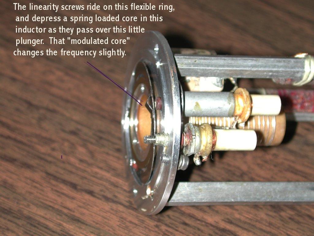
The Cosmos PTO is one of several (Collins, Motorola, etc.)PTO's made for the R-390A. It has a unique linearity adjustment feature thatuses 48 very small adjustment screws on a corrector disk that rotates slowly asthe PTO is tuned. These screws ride on a circular ring slide that in turn"modulates" a spring loaded plunger in a small coil that is in series with themain tuning coil. These "modulations" change as the shaft rotates and slightlyvary the oscillator frequency depending on the screw settings. It's possible toget very good linearity with this technique. Other PTO manufacturers useddifferent techniques. I won't go into any more theory of operation ormaintenance, there are a couple of web pages about Cosmos adjustment (
Chuck Rippel's page hasseveral links), such as Cosmos alignment articles already written about theCosmos PTO by
JohnHarvie and
TomMarcotte. All of these references were helpful to me in this project.Electric Radio Issues 30 and 31 also include PTO articles by Osterwald (I don'thave these so I am not sure if they covered just the Collins PTO or theCosmos.). The R-390A Video Tape series also has some very good information onthese PTOs and how to open and service them. Also I don't know the "official"names of various components in the PTO, so I am making them up as I go along(such as the "corrector disk").
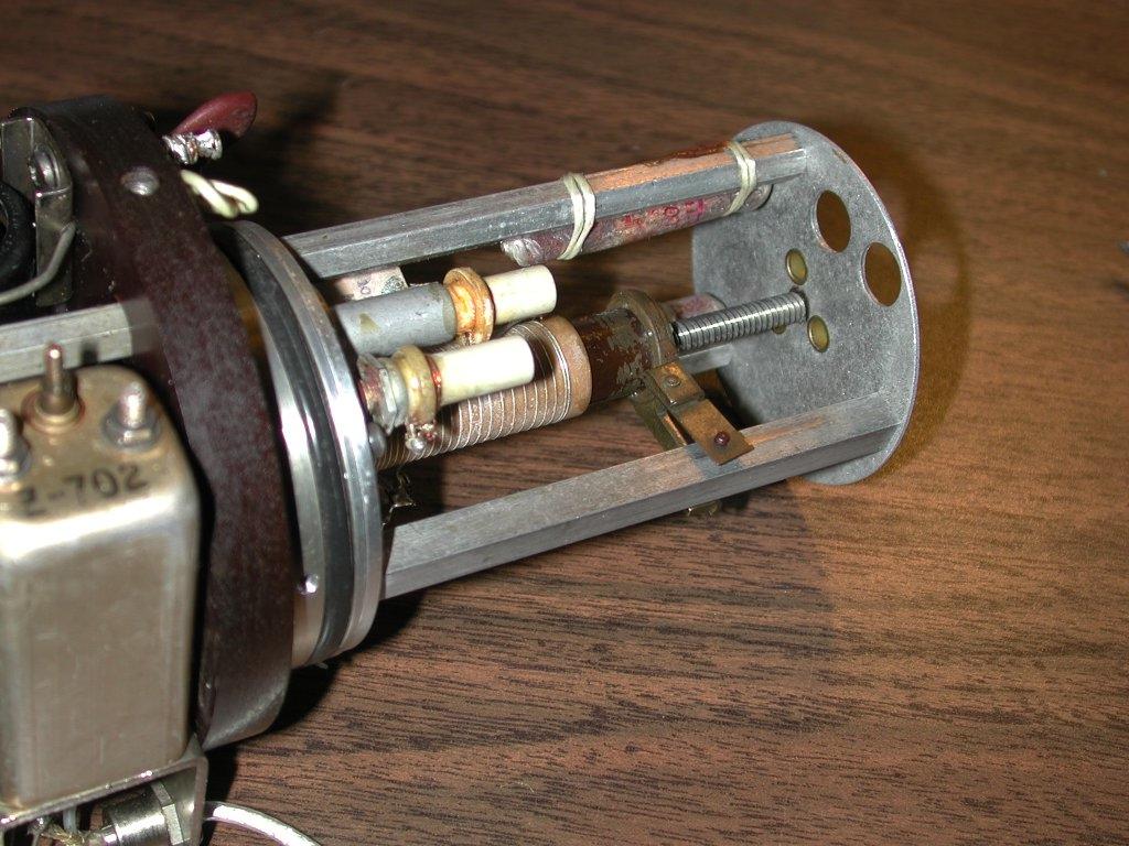
When I first opened the PTO, it looked like the lead screw wasnot thoroughly mating with the fiber bearing plate in the rear. In fact the endof the shaft was dangling in mid air about 1/8 inch away from its bearing plate.If I pushed in on the shaft from the front, it would move backward and mateproperly. But then it would eventually work its way out again unless held inplace. This did not seem right at all. Why was the shaft able to slide thatmuch? The picture below shows the lead screw properly mated with the bearingplate as it should be. (Note: Having never seen another Cosmos PTO, I can onlyassume this is the proper configuration. The R-390A video series does seem toshow the shaft being inserted into the bearing plate in this manner).
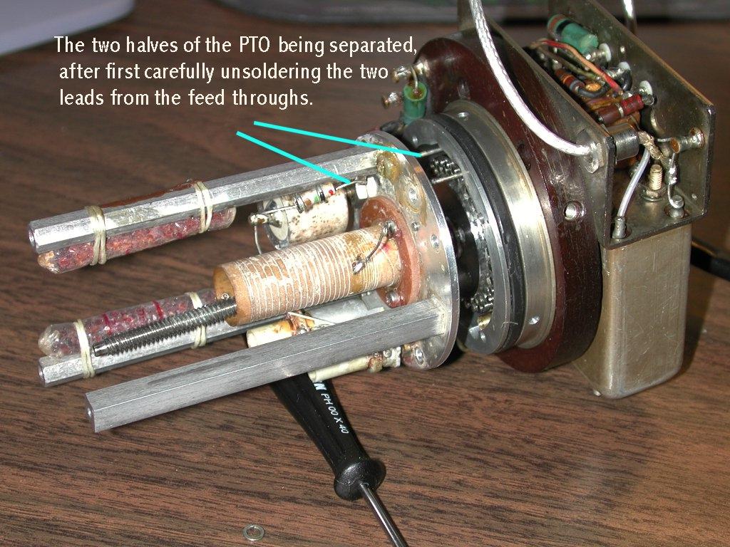
Since the corrector disk was slipping and the shaft was loose, I suspectedsomething amiss in that area. But to get to it, I had to go to the inner sanctumof inner sanctums. But even that turned out to be fairly straightforward. Fourscrews hold the PTO coil assembly to the front part. In between these two halvesis a cavity that houses the corrector disk and associated stuff. I unsolderedthe two leads from the PTO that attach to a couple of feed throughs first (seebelow), removed the 4 mounting screws and gently pulled the two halves apart.Had to get all the solder off the feed through pins so they would pass throughthe insulating grommets. See figure below. If you look carefully in the openingbetween the two parts, you can begin to see the small disk and its 48 linearityadjustment screws.
Once the two halves are apart, you can easily see just how the corrector diskwith its 48 adjustment screws works in conjunction with a flexible ring (on theopposite half of the PTO) to continuously adjust or modulate the little seriescoil with its spring loaded core and plunger. Every 25 khz, the tuning istweaked slightly by these screws to compensate for non-linearities in the maincoil. With the PTO assembled and closed up, these screws have to each beadjusted by hand using a frequency reference or counter to establish thelinearity. An external access port is provided for this purpose. (Even thoughthere are 48 screws shown on this disk, only 40 of them will actually beeffective within the 10 turns from 2455 to 3455 khz.).
Opposite this disk of screws is the flexible slide ring and spring loadedplunger that continuously adjusts the compensating coil core. Note that thesecond small coil shown is another compensating coil used to establish endpoints, i.e. to adjust the tuning so that the PTO goes from 2455 khz to 3455 khzin exactly 10 turns. This end point adjustment is typically made beforeadjusting the linearity screws, but usually has to be revisited afterwards.
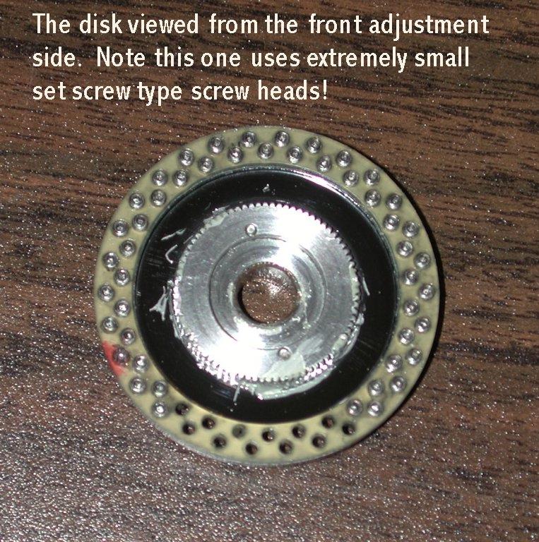
Here are pictures of the disk after removal. I understand that most Cosmosdisks use regular flat head screws. Mine, unfortunately, has some really hideoussuper microscopic set screw heads, like miniature splines or torx heads. Nothingon the planet could be found to fit. So out came the file and magnifying glassand several hours later an old jewelers .04 driver was refashioned intosomething that would work more or less. While the disk was out, I worked thescrews a little to loosen them up (one was stuck and still is to this day). ThenI backed them all off fully counterclockwise, then one turn clockwise as astarting point. As it turns out, this put each of my tuning points about 3 khztoo high. After reassembly, clockwise rotations of each screw brings theoscillator frequency down 3-5 khz., and an accurate counter is used to adjusteach screw every 25 khz (or every 90 degrees of rotation).

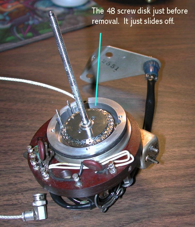
Now for the problem at hand. The disk was slipping. So it hadto come out (it just slides off the shaft), revealing the watchwork gearingbehind it that makes it rotate at about 1/10th the rotation of the lead screw(it makes about one complete revolution for each 10 turns of the main shaft).Herein was the culprit.

A collar that the disk slides onto, and which also contains aset of gear teeth that drive the larger gear wheel, had broken loose from itsmoorings on the lead screw. It is apparently supposed to be spot welded to thelead screw as one piece. It not only drives the disk, but also secures the shaftlengthwise so it doesn't slide in and out. The weld had broken, allowing thecollar to slip freely. How in the world do you reattach a collar without gummingup the delicate workings around it? I didn't have the high-tech welder or bonderthat was originally used. The only solution I could come up with was to createsome artificial "knurlings" around the lead screw so that when the collar wasslipped over them, it would be held in place by friction. So I did that byremoving the collar, and very carefully using some dikes, just enough to roughup the surface of the lead screw exactly where the collar would sit. Thensliding the collar back on, of course the knurlings wouldn't let it slip oneasily. Some heat from the soldering iron expanded the collar just enough toallow it to be tapped on over the knurlings. Then after it cooled and contractedaround the shaft, bingo, it became securely held in place.
Now everything had to be put back together again and adjusted.I wasn't out of the woods yet. One thing is critical. You will note that some ofthe screw holes on the disk in my PTO were vacant. The disk has to bereinstalled in the proper orientation so that when the PTO tuning core isscrewed back onto the shaft and in its resting position, the disk is"synchronized" mechanically with it. Otherwise, you could end up staring at someempty screw holes as you try to bring in the frequency during the adjustmentprocess. In my case this was a little trial and error, and several re-openings,but I finally did find that if I first set the disk so that the 15th screw fromthe clockwise end (or was it counter clockwise?) was visible in the access port,then started turning the core back onto the lead screw at that point, then whenthe core was back where it was supposed to be, all was well. Just hold the coreby hand and turn the shaft clockwise and let the core ride back to properposition.
Fortunately it went together reasonably well. But on its firsttest it wouldn't oscillate! I re-opened it and discovered that I had managed tobreak the center tap wire off of the main coil (it was one of those two leads tothe feed-throughs I was supposed to remove
carefully!) Some microscopicsoldering and a little epoxy cement fixed that, and we were back in businessagain.
The picture below shows the reassembled Cosmos PTO and its twoadjustment ports in the front. On the right is the end point adjustment coil.This is used to set it so that exactly 10 turns of the shaft moves theoscillator from 2455 to 3455 exactly. Left of that is the port where you accessthe linearity screws. As you turn the shaft, the disk rotates behind this portand at each 90 degree (or 25 khz) another screw is centered in the window foradjustment.

A time consuming process but it worked! As said before thereare various pages and articles describing this adjustment procedure, as well asend point adjustment, so I won't repeat it here. Just be prepared to sit for along time and get neck cramps.
Was it worth it? You bet! In the end I am very happy with myPTO now, and the linearity is excellent. But as I said before, don't do thisunless you
really need to.

