Station Description
DRAFT DOCUMENT – NOT FINAL
This document describes the equipment that will be provided to teams for WRTC2014.
All competitors will be located in the same geographical region with similar topography. Competitor location-s will be separated by a minimum of 500 meters.
WRTC2014 will be a Field Day style competition. Equipment that will be installed by the organizers at each site:
•*42-foot tower with an antenna rotator and control unit.
•* 20/15/10 m Cycle 24 TX38 tri-bander with one feed line and PL-259 male connector. Antenna manual:
http://www.cycle-24.com/tx38.html•* 40 m Inverted-V dipole with feed line and PL-259 male connector.
•* 80 m Inverted-V dipole with feed line and PL-259 male connector.
•* 2 x 100 watt peak power monitors
Peak power monitors act on forward power only, which is greater than transmitted power when SWR > 1. In order to transmit 100 W to a mismatched antenna, an external tuner may be needed to bring the SWR down, thus avoiding premature triggering of the power monitor.
•* 2 PL259-PL259 jumpers for connecting peak power monitors.
•* 9’x 13′ Tent
•* 2 KW Power Generator with power cable going to the tent.
No Uninterruptable Power Supplies, 12 V accumulator batteries or similar power sources are allowed for power backup. Exception: built-in batteries in portable computers, audio recorder, or other peripherals. CMOS memory backup batteries are allowed.
•* 8 gallon-s of gasoline for generator
•1 ground rod driven nearby and connected to the generator and 1 ground rod with grounding strip driven nearby tent for inside connection.
•3 x 5-outlet 110VAC strips
•*2 electric lamps
•* 1 Electric Fan
•* 3 portable tables
•* 3 plastic chairs
•WC cabin with hand wash facilities
•8 gallon-s of drinking water
•Food and snacks
Competitors are not allowed to substitute equipment marked with an asterisk (*) with any other equipment unless permission is given by the organizing committee.
Since this is a field day style operation each team will have a generator which has to be filled with gasoline. To avoid team members spending their time re-filling the generator, the organizers will provide dedicated volunteers at every location to ensure the generator is kept running during the contest period.
Triplexer
It is highly recommended, but not required, that each team provide a “triplexer” device for the triband antenna. The function of the triplexer is to provide discreet band ouputs using one coaxial feed. This allows operation of the tri-band antenna on two bands simultaneously.
It is up to the team to provide such a device, but it must not amplify the signal in any way.
Example of triplexers for purchase can be found here:
http://www.inrad.net/files/Pubs/HF-Triplexer-Instruction-Manual.pdf or
http://www.dunestar.com/dunestar-M333a1-manual.pdf For details on building your own triplexer, refer to June 2010 QST “HF Yagi Triplexer Especially for ARRL Field Day”. By K6KV
Typical SWR vs. frequency curves for TX-38 tri-band antenna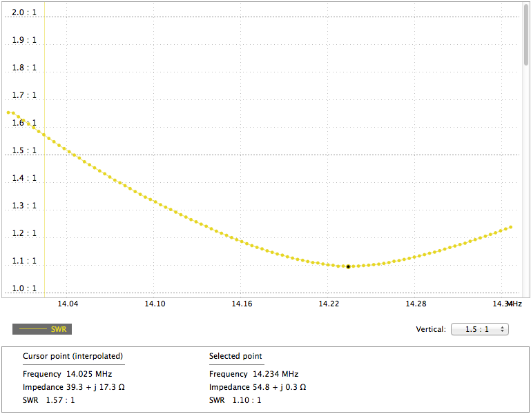
TX-38 SWR 20 meters
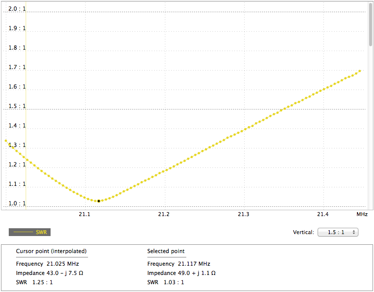
TX-38 SWR 15 meters
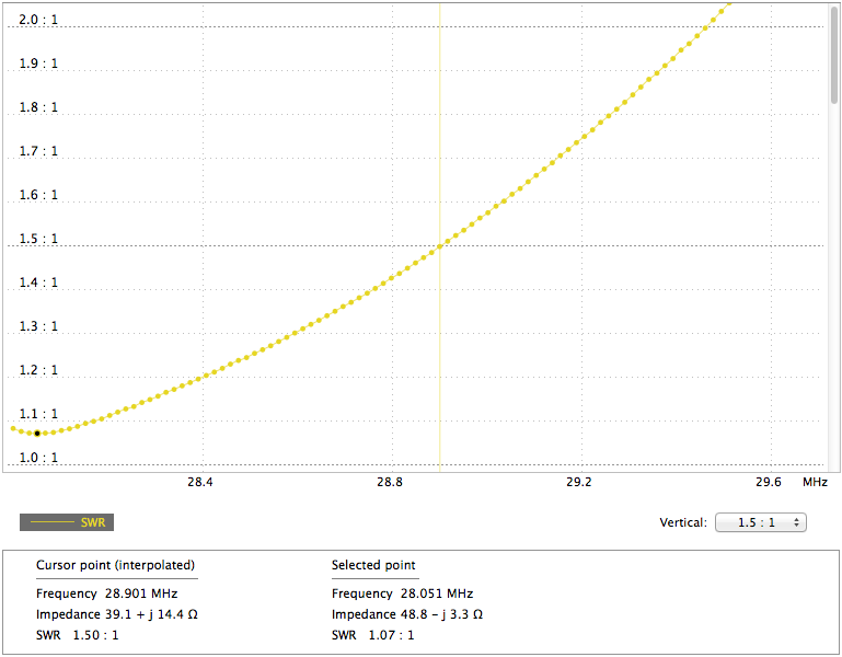
TX-38 SWR 10 meters

