论坛风格切换切换到宽版
  • 10853阅读
  • 23回复

R-390A的维护校正过程 [复制链接]

上一主题 下一主题
离线BD1CM
 
发帖
3306
只看楼主 倒序阅读 0楼 发表于: 2012-11-23
    由于搞SDR需要找对比对象,就下狠心从美帝搞了台R-390A回来。买SSD009也是需要进行对比才购进的。
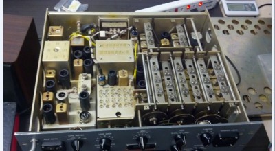
初步测试R-390A的灵敏度比SSD009高了10分贝不止。我这个R-390A是1962年制造,到今年整50年了,
开机工作一切正常。但是考虑到年代久远,各个频点晶振、滤波通道,BFO振荡器需要进行维护校正了,所以准备
按照美帝原来的手册进行校正维护,这是一个比较慢长复杂的过程,美帝的手册上有些提到的设备我也没有,所以按照
自己的理解使用其他仪器进行测试。
  这个帖子可能会根据我这台机器的实际情况发展跳过R-390A手册上一些校准步骤,也可能多出来一些自身发挥的东西。
我希望我这台R-390A能够在SDR研发过程结束前进入工作状态,以便进行对比测试。
http://www.r-390a.net/
是维护资料的来源网站


单独的接收机或发射机比收发一体机相对来说好修就是通道单向的简单易懂。
校准按照美帝的手册第六章开始了


6.1 Introduction
6.1.1
This Chapter provides alignment and repair procedures to enable maintenance personnel to correct deficiencies found as a result of scheduled maintenance and troubleshooting procedures in Chapter 4 and 5 respectively. Before any alignment is attempted all faulty components should be located and replaced. A definite need for alignment should be established by accomplishing sensitivity and bandwidth tests (paragraphs 4.3.1 and 4.3.2) after eliminating faulty components.
6.1.2
The alignment section describes the recommended method by which the equipment is set up, test equipment is connected and used, and necessary adjustments are made to ensure proper equipment performance
6.1.3
The repair section outlines the methods necessary for disassembly, cleaning, repairing, and reassembly required to replace a faulty component within the receiver.
6.2 Alignment and Adjustment Procedures
6.2.1 General Alignment Information
se a fluted no. 8 Bristol wrench for adjusting the antenna, the RF, and the variable IF cores. Use the same tool for adjusting the tuning shafts during mechanical synchronization. Use a nonmetallic screwdriver for adjusting the various trimmer capacitors. Use a hexagonal, nonmetallic tool for adjusting the cores in T501, T502, T503, and Z503 on the IF subchassis. Be sure that this tool is inserted through the top core into the bottom core, and that the bottom core turns without disturbing the setting of the top core. Make this type of adjustment only after the particular coil or transformer has been replaced.
6.2.2 Test Equipment and Special Tools
1. RF Signal Generator AN/URM-25
2. Impedance Adapter MX-1487/U
3. Electronic Multimeter AN/USM-116
4. Multimeter AN/PSM-4
6.2.3 Test Conditions
1. Temperature: Normal room or shelter.
2. Humidity: Normal room or shelter.
3. Line Voltage and Frequency: 115 or 230 volts ac ± 1 percent at 60 Hz.
使用合适的电源(电源电压的调整请看相关电源单元的连接方法,解决110V与220V的转换问题)
4. Warm-up Period: At least 15 minutes.
预热15分钟以上
5. Standard Modulation: 30 percent AM at 400 Hz.


[ 此帖被BD1CM在2012-11-23 18:48重新编辑 ]
uH = 25330/ (MHZ x MHZ x pF).  pF = 25330/( MHZ x MHZ x uH).
严肃认真、周到细致、稳妥可靠、万无一失,虽然我们可能做不到万无一失,但是我们尽人事、听天命……

https://uk.groups.yahoo.com/neo/groups/S9-C_SDR/info


QQ:63545177
离线BD1CM
发帖
3306
只看该作者 1楼 发表于: 2012-11-23


6.2.4 Preparation for Alignment
Before applying power to the receiver, the following conditions must exist:
开机前请确认以下事项
1. All the controls must operate freely and the knobs must be securely attached to their shafts.
所有旋钮运转自如
2. The tubes and tube shields must be securely in place.
电子管牢靠的在应在位置
3. All connectors must be seated firmly.
所有连接器连接正常
4. The KILOCYCLE CHANGE dial overtravel must not be less than 25 kHz at each end.
KC旋钮距离两个端点25KC以上
5. The receiver must be grounded, and ac power must be applied; the front-panel controls must be set according to table 4-2.
接收机必须接地,并使用交流电源,前面板控制参看表4-2
6. The B+ voltage between chassis ground and the +150V test point E607 (figure 6-28) should be between +148 volts and +153 volts.
R607测试点处B+对地电压为+150V,148V~+153V为合格
7. All tube filaments must be lit.
所有灯丝必须能点亮(待机模式除外)
8. The antenna relay must be actuated when the FUNCTION switch is placed in the STANDBY and CAL positions.
主功能开关在待机及校正模式时天线继电器应可有效动作
9. CARR-METER ADJ control R523 (figure 6-16) on the IF subchassis must be adjusted for a CARRIER LEVEL meter indication of 0.
通过调整IF单元上的R-523电位器,调整载波幅度指示表指示为0
6.2.5 Mechanical and Electrical Synchronization
机电同步
The receiver tuning elements, which consist of the frequency indicator, KILOCYCLE CHANGE, and MEGACYCLE CHANGE 10-turn stops, the 6-position RF band switch, the second crystal band switch, and the VFO, must be in synchronization with the RF gear train before electrical alignment is attempted. If the receiver is being realigned because of low sensitivity or replacement of parts such as the variable IF, the fixed IF, or the RF transformers, it should not be necessary to check the mechanical and electrical synchronization. Nonsynchronization of the tuning shafts and the RF gear train is likely to occur as a result of the removal and replacement of the RF subchassis, crystal-oscillator subchassis, VFO subchassis, or the disassembly of part or all of the RF gear train assembly. Check and adjust the following items as may be necessary.
接收机调谐单元,包括频率指示器千周调节钮兆周调节钮6档位射频波段开关二组晶振波段开关,以及VFO振荡器,这些都必须同步工作。如果发生更换RF、IF、VFO、晶振单元元件或一些变压器及电容的调整后造成的灵敏度下降的情况,就应当考虑进行如下校正操作(此处不一定按原文翻译)。
6.2.5.1
Ten-Turn Stops. Check the 10-turn stops (figure 6-3) by rotating the MEGACYCLE CHANGE and KILOCYCLE CHANGE shafts fully counterclockwise. The first two digits on the frequency indicator should indicate halfway between 32 and 00 MHz (off the detent position). The next three digits should indicate between +30 and -970 kHz.
旋转MC(MHz)旋钮齐指示范围应为0-32,旋转KC(KHz)旋钮 应为+30~-970KC之间
(R-390A的KC指示前面有个+ -号,在正常的000-999Kc内没有指示,如果用户继续向两边旋转将出现相应的指示符号,
到达两边极限后MC刻度不会跟随旋转需要用户另行旋转MC进行切换MHz频率)


[ 此帖被BD1CM在2012-11-23 15:18重新编辑 ]
uH = 25330/ (MHZ x MHZ x pF).  pF = 25330/( MHZ x MHZ x uH).
严肃认真、周到细致、稳妥可靠、万无一失,虽然我们可能做不到万无一失,但是我们尽人事、听天命……

https://uk.groups.yahoo.com/neo/groups/S9-C_SDR/info


QQ:63545177
离线BD1CM
发帖
3306
只看该作者 2楼 发表于: 2012-11-23

6.2.5.2
Slug-Rack Cams and Followers. (See figure 6-2.) Check the slug-rack cam followers at the high and low ends of each coil range. Normally, all cam followers should be near (but not at) the peak of the cams at the high end of the coil ranges.
凸轮与随动器,检查凸轮追随器以及线圈在高端和低端的位置通常,调感线圈的高端并不是凸轮的最高端
⇒ Note:
If the cam followers do not function as described below, follow repair procedure in paragraphs 6.3.16 through 6.3.19.

注意
如果凸轮的追随器不能如下所述后续维修程序见6.3.16至6.3.19
1. All cam followers, except the cams for the 0.5- to 1-MHz range, should not quite reach the peak of the cams at the high end of the range.

2. The cam followers for the 0.5- to 1-MHz range may pass over the peak of the cams for a KILOCYCLE CHANGE control reading of +025 or higher.

3. All cam followers except the 0.5- to 1-MHz cam followers should not quite reach the valley of the cams as the KILOCYCLE CHANGE control is turned to the low end of the coil range.

4. The 0.5- to 1-MHz cam followers may pass through the valley and start up the other side of the cams as the KILOCYCLE CHANGE control is adjusted to a reading of about 475.

5. The cam follower on first variable IF transformer Z213 (17.5 to 25 MHz) is near the valley of the cam when the KILOCYCLE CHANGE control reading is 500, and rises to near the peak at 07 +000.

6. The cam follower on second variable IF transformer Z216 (3 to 2 MHz) is near the valley of the cam when the KILOCYCLE CHANGE control is rotated fully clockwise, and near the peak when the KILOCYCLE CHANGE control is fully counterclockwise.

这一段翻译很蹩脚,主要是说在一些频率范围哪些凸轮随动器应该怎么工作,而不应该出现什么情况的。
我的390貌似这里比较正常,就不再翻译了。


[ 此帖被BD1CM在2012-11-23 17:50重新编辑 ]
uH = 25330/ (MHZ x MHZ x pF).  pF = 25330/( MHZ x MHZ x uH).
严肃认真、周到细致、稳妥可靠、万无一失,虽然我们可能做不到万无一失,但是我们尽人事、听天命……

https://uk.groups.yahoo.com/neo/groups/S9-C_SDR/info


QQ:63545177
离线bh7pvb
发帖
97
只看该作者 3楼 发表于: 2012-11-23
      
离线BD1CM
发帖
3306
只看该作者 4楼 发表于: 2012-11-23
6.2.5.3 Camshafts.
⇒ Note:
If any cams have been synchronized with the RF subchassis removed from the main frame, the VFO subchassis must be synchronized (par 6.2.5.6) after the RF subchassis is replaced.
1. Set the MEGACYCLE CHANGE and KILOCYCLE CHANGE controls for a frequency-indicator reading of 7+000. The camshafts are synchronized if the cam positioning marks on the pressed cam plates line up with the points of the cams and the intermittent switch drive gears. Figure 6-2 shows the front and figure 6-13 shows the rear of the cam plate.
2. If all the cams line up at some other frequency indications, perform the following:
a) Position the MEGACYCLE CHANGE and KILOCYCLE CHANGE controls until the cam points are lined up with the cam positioning marks.
b) Loosen the two bevel gear clamps on the mechanical counter (figure 6-1).
c) Manually adjust the counter dial to 07 +000.
d) Tighten the gear clamps.
3. If one cam does not line up with the cam position mark, perform the following:
1. Loosen the clamp on the front end of the individual camshaft.
2. Line up the cam point with the cam positioning mark.
3. Tighten the clamp.
⇒ Note:
To avoid losing the nut, do not loosen the clamp more than necessary. Be careful not to strip the screw thread when tightening.
这段是说如果凸轮轴从主体重新拆装过,那么需要按这些步骤重新装配。
三大点注意 1、很多消回差齿轮重新装配时要注意使其处于预紧状态  
                   2、那个唯一的特殊齿轮在7.000MHz时与其属小齿轮的相互状态
                   3、那些凸轮在某频率时应有的位置(凸轮最突出处及对位小孔与机架上的黑线的相对位置)
uH = 25330/ (MHZ x MHZ x pF).  pF = 25330/( MHZ x MHZ x uH).
严肃认真、周到细致、稳妥可靠、万无一失,虽然我们可能做不到万无一失,但是我们尽人事、听天命……

https://uk.groups.yahoo.com/neo/groups/S9-C_SDR/info


QQ:63545177
离线BD1CM
发帖
3306
只看该作者 5楼 发表于: 2012-11-23
6.2.5.4 Six-Position RF Band Switch. (See figure 6-20.)
6波段开关
1. Position the MEGACYCLE CHANGE and KILOCYCLE CHANGE controls for a frequency-Indicator reading of 07 +000.
将频率设定在07.+000MHz 注意+000而不是000
2. Remove V207.
拔除V207 本振管
3. Disconnect P108 (figure 6-14) from J208.
将P108从J208上断开
4. Connect Multimeter AN/PSM-4 ( ) between pin 6 of XV207 and pin D of J208. The Indication should be approximately 200k ohms after Field Change 7 has been accomplished.
将电阻表接于V207 PIN6 与J208 PIND之间应大于200K
5. Turn the MEGACYCLE CHANGE control to 08. The AN/PSM-4 ( ) should indicate an infinite reading.
将MC旋钮调整到08 电阻表应读数为无限大
6. If the indications are not as in 4 and 5 above, continue with procedures 7, 8, and 9.
如果不如4、5步所述请执行第7、8、9步
7. Disconnect the PSM-4 ( ) and reinsert V207.
断开电阻表并插入V207
8. Remove the front panel (paragraph 6.3.2) and the RF subchassis (paragraph 6.3.3).
拆除前面板和RF单元(这活大了,能不做就不做这件事)
9. Loosen the RF band switch clamp (figure 6-3). Turn the band switch shaft until the rotors are centered on the contacts, which provide the indications required in procedures 4 and 5 above. Tighten the RF band switch clamp.
松开射频波段开关图6 - 3波段开关转子中心的联系达到所需特征步骤4和5以上拧紧射频波段开关


瞧V207藏那地方,真难拆
貌似我的机器这点正常,所以就不折腾这段了

[ 此帖被BD1CM在2012-11-23 18:24重新编辑 ]
uH = 25330/ (MHZ x MHZ x pF).  pF = 25330/( MHZ x MHZ x uH).
严肃认真、周到细致、稳妥可靠、万无一失,虽然我们可能做不到万无一失,但是我们尽人事、听天命……

https://uk.groups.yahoo.com/neo/groups/S9-C_SDR/info


QQ:63545177
离线zsh
发帖
1360
只看该作者 6楼 发表于: 2012-11-23
哈哈哈 支持........................!
我是中国最特殊的HAM之一 嘿嘿
革命尚未成功  HAM應需努力
致力于收集共享设备技术维修手册软件...........
个人业余电台呼号:BD7OA(EX:BG2IJJ)
诚实、守信、开拓、进取。73!  
网名叫:金阿甘 QQ:444341969
MSN:zshdodo@hotmail.com
网店:https://shop136258697.taobao.com
Blog:http://blog.sina.com.cn/radionew
Blog:http://www.radionew.com.cn/
手机:壹伍玖 0432 5198 只收短信
电邮:zsh518@gmail/126.com
住址与通信地址:请在www.qrz.cn用BG2IJJ/7查!
本人目前在七区!!!
离线BD1CM
发帖
3306
只看该作者 7楼 发表于: 2012-11-23
回 zsh 的帖子
zsh:哈哈哈 支持........................! (2012-11-23 18:08) 

咱们成同好了
uH = 25330/ (MHZ x MHZ x pF).  pF = 25330/( MHZ x MHZ x uH).
严肃认真、周到细致、稳妥可靠、万无一失,虽然我们可能做不到万无一失,但是我们尽人事、听天命……

https://uk.groups.yahoo.com/neo/groups/S9-C_SDR/info


QQ:63545177
离线BD1CM
发帖
3306
只看该作者 8楼 发表于: 2012-11-23
6.2.5.5 Crystal-Oscillator Subchassis Band Switch
晶体振荡器单元波段开关
1. The crystal-oscillator band switch is synchronized when the indicator-wheel number (figure 6-14) that appears in the hole on the crystal-oscillator subchassis agrees with the first two digits of the frequency indicator.
1。晶体振荡器波段开关同步时,MC旋钮的读数与,晶振单元的读数一致

⇒ Note:
Only even numbers appear on the indicator wheel; odd numbers appear as straight lines between numbers; 00 on the frequency indicator appears as 0.

⇒注意
只有偶数出现在指示轮奇数出现在数字之间的直线00频率指示器显示为0
2. If the indication is incorrect set the receiver controls as directed in paragraph 5.5.2 and turn the FUNCTION switch to STANDBY.
2。如果指示不正确设置接收机控制的指示5.5.2并将功能切换到备用

3. Connect Electronic Multimeter AN/USM-116 ( ) between test point E210 (figure 6-19) and chassis ground.
将电压表接到E210与地线之间
4. Loosen the shaft coupler. Insert a long screwdriver through the SYNC XTAL OSC hole in the rear panel of the receiver and turn the crystal-oscillator band switch shaft to the correct number.
4。松开耦合器插入长螺丝刀通过同步石英晶体振荡器后面板上的接收器和石英电子波段开关转动到正确的号码

5. Tighten the shaft coupler.
5。拧紧耦合器

6. Turn the MEGACYCLE CHANGE control to each side of the detent point. The AN/USM-116 ( ) indication should be -3.5 to -8 volts at the detent point and should drop to zero each side
of the detent point. If not, readjust the crystal-oscillator band switch shaft (4 and 5 above) to meet this condition.
6。MC旋钮的每个制动点。电压表指示应该是- 3.5到- 8伏如果不是调整晶振单元波段开关满足这一条件
7. Disconnect the AN/USM-116 ( ).
断开电压表


洞洞里的8就是对应MC读数的8MHz了,那堆电容可不是调节频率的,而是调节振荡器幅度的,
这一点很郁闷,390的频率校正就靠晶体自己了,准就准了不准直接换。
这里我的机器机械部分也比较正常所以跳过不拆
[ 此帖被BD1CM在2012-11-23 18:50重新编辑 ]
uH = 25330/ (MHZ x MHZ x pF).  pF = 25330/( MHZ x MHZ x uH).
严肃认真、周到细致、稳妥可靠、万无一失,虽然我们可能做不到万无一失,但是我们尽人事、听天命……

https://uk.groups.yahoo.com/neo/groups/S9-C_SDR/info


QQ:63545177
离线BA7KW
发帖
16344
只看该作者 9楼 发表于: 2012-11-23
神器啊!!我在广州见过R391,那简直是艺术品啊!
BA7KW  张建华
BA7KW"at"163.com
离线BD1CM
发帖
3306
只看该作者 10楼 发表于: 2012-11-23
回 BA7KW 的帖子
BA7KW:神器啊!!我在广州见过R391,那简直是艺术品啊! (2012-11-23 20:25) 

那些机械随动的跟踪调谐部分随着旋钮一起运动的时候,那种感觉实在美极了。
uH = 25330/ (MHZ x MHZ x pF).  pF = 25330/( MHZ x MHZ x uH).
严肃认真、周到细致、稳妥可靠、万无一失,虽然我们可能做不到万无一失,但是我们尽人事、听天命……

https://uk.groups.yahoo.com/neo/groups/S9-C_SDR/info


QQ:63545177
离线bjadsl
发帖
287
只看该作者 11楼 发表于: 2012-11-26
神机。。。。。。。。。。。
离线BD1CM
发帖
3306
只看该作者 12楼 发表于: 2012-11-27
等待复刻的KC旋钮中,没有这钮调起来真费劲
uH = 25330/ (MHZ x MHZ x pF).  pF = 25330/( MHZ x MHZ x uH).
严肃认真、周到细致、稳妥可靠、万无一失,虽然我们可能做不到万无一失,但是我们尽人事、听天命……

https://uk.groups.yahoo.com/neo/groups/S9-C_SDR/info


QQ:63545177
离线BD1CM
发帖
3306
只看该作者 13楼 发表于: 2012-12-01

复刻成功,新老大钮换岗!
uH = 25330/ (MHZ x MHZ x pF).  pF = 25330/( MHZ x MHZ x uH).
严肃认真、周到细致、稳妥可靠、万无一失,虽然我们可能做不到万无一失,但是我们尽人事、听天命……

https://uk.groups.yahoo.com/neo/groups/S9-C_SDR/info


QQ:63545177
离线BD1CM
发帖
3306
只看该作者 14楼 发表于: 2012-12-01
经过初步试验我这台390A的PTO 需要校正了,1MHz内偏差10Kz,的研究下怎么校正这个PTO了,看来有点难度
uH = 25330/ (MHZ x MHZ x pF).  pF = 25330/( MHZ x MHZ x uH).
严肃认真、周到细致、稳妥可靠、万无一失,虽然我们可能做不到万无一失,但是我们尽人事、听天命……

https://uk.groups.yahoo.com/neo/groups/S9-C_SDR/info


QQ:63545177
离线BD1CM
发帖
3306
只看该作者 15楼 发表于: 2012-12-01


6.2.5.6
VFO Tuning Shaft
1. Preset the receiver (paragraph 5.5.2). Turn the FUNCTION switch to MGC. Allow 15 minutes for warm-up.
2. Tune the receiver to station WWV or a local station of known frequency. Be sure to set the frequency indicator exactly to the station’s assigned frequency.
3. Turn the BANDWIDTH switch to 1.
4. Remove the antibacklash spring on the Oldham coupler (figure 6-4) and loosen the VFO (figure 6-15) shaft clamp nearest the front panel.
⇒ Caution:
The VFO will be permanently damaged if the shaft is turned too far in either direction. The end of shaft travel can be felt while turning the shaft with the fingers. Do not force the shaft.
5. Holding the VFO shaft steady, turn the shaft until the station is tuned for maximum loudness.
6. Tighten the shaft coupler and replace the anti-backlash spring.
7. With the first two digits of the frequency indicator set at any position except 00, check the receiver calibration at the low, middle, and high frequency end of the band.

这段的意思是在手动增益(MGC)状态时,利用已知频率的发射台,在带宽1K时靠听音量大小来校正VFO连接器的偏差,但是这么做首先要保证VFO还是线性的。
就是要在某一MHz波段内大高、中、低三点进行检查,这段还没有涉及VFO(PTO)非线性校正问题。


[ 此帖被BD1CM在2012-12-01 18:00重新编辑 ]
uH = 25330/ (MHZ x MHZ x pF).  pF = 25330/( MHZ x MHZ x uH).
严肃认真、周到细致、稳妥可靠、万无一失,虽然我们可能做不到万无一失,但是我们尽人事、听天命……

https://uk.groups.yahoo.com/neo/groups/S9-C_SDR/info


QQ:63545177
离线BD1CM
发帖
3306
只看该作者 16楼 发表于: 2012-12-01
6.2.6 Adjusting ZERO ADJ Control
heck the adjustment of the ZERO ADJ control as follows:
1. Turn the ZERO ADJ knob fully counterclockwise. Slowly turn the knob clockwise and observe the free play in the knob. The free play should be approximately 1/8 turn.
2. If there is no free play, or if the free play is excessive, remove the knob.
3. With the thumb and forefinger, adjust the shaft for approximately 1/8-turn free play.
4. Replace the knob so that the stop on the rear of the knob is directly to the right of, and touching the finger on, the ZERO ADJ control locking washer on the front panel. Tighten the knob.
5. Turn the ZERO ADJ control fully clockwise to the stop, and check to see that the locked clutch gear assembly (figure 6-1) is disengaged. Do this by rocking the KILOCYCLE CHANGE control back and forth and observing the reading of the frequency indicator to see that it does not change.
6. Turn the ZERO ADJ control fully counterclockwise to the stop and recheck for approximately 1/8-turn free play.
7. Repeat the procedures in 2 through 6 above if the free play and clutch disengagement are not as specified.

0位调整旋钮的检查与修复功能,这个旋钮允许在大约15K范围内将实际频率与度盘读数进行对正。
此旋钮正常工作时,的使用方法如下比如某电台频率为 14.180MHz 但是我们实际接收时度盘读数为14.185MHz ,那么先将度盘调整到14.180MHz后,顺时针旋紧ZERO ADJ旋钮,
此时在小范围旋转KC旋钮时度盘将不会转动,但是PTO(VFO)还是会动的,此时将接收频率与电台实际频率对正后,逆时针旋转ZERO ADJ旋钮后,这个电台的频率读数就是14.180MHz了

[ 此帖被BD1CM在2012-12-01 18:23重新编辑 ]
uH = 25330/ (MHZ x MHZ x pF).  pF = 25330/( MHZ x MHZ x uH).
严肃认真、周到细致、稳妥可靠、万无一失,虽然我们可能做不到万无一失,但是我们尽人事、听天命……

https://uk.groups.yahoo.com/neo/groups/S9-C_SDR/info


QQ:63545177
离线BG8SF
发帖
4683
只看该作者 17楼 发表于: 2012-12-05
帝国主义的毒物被LZ弄来开膛破肚了!
离线恆通水产
只看该作者 18楼 发表于: 2013-01-22
这个好.要学习.我边学边试.
离线BH7IPB
发帖
31
只看该作者 19楼 发表于: 2013-10-11
进来学习,有机会也搞一台。